
Meubles artisanaux
Outil à canneler Patent Pending.

Les deux bouts du câble sont fixés, après quelques enroulements dans le sens contraire, de chaque côté de la gorge de la poulie. La poulie est attachée à la tête du tour par un collet de serrage.

L'accès à la vis du collet se fait par un trou pratiqué dans la gorge de la poulie.

Pour plus de sécurité, on peut relâcher la tension sur les courroies d'entraînement du tour.

Des poulies de différents diamètres permettent de varier le pas de la spirale de la cannelure.


Les deux renvois qui enlignent le câble de chaque côté de la poulie sont montés, avec le tube, sur un socle qui peut-être déplacé d'avant en arrière pour s'adapter à des pièces de différents diamètres ou de forme conique.

La poulie de renvoi met le câble sous tension. Le tube stabilise le déplacement du chariot. Les deux sont montés sur un petit socle qui peut être déplacé d'avant en arrière pour s'adapter à des pièces de différents diamètres.


Pour canneler une pièce non-linéaire, le tube est enlevé et le chariot est guidé par un petit téton situé à la base du chariot qui glisse contre un gabarit fixé à la table, gabarit qui épouse exactement le galbe de la pièce à tailler.
Une possible amélioration au système serait de monter la toupie au chariot par une petite pièce mobile qui permettrait de dégager la mèche lors de la ré-indexation de la pièce à canneler sans que la cannelure aille jusqu'au bout de la pièce. Présentement si on veut arrêter la coupe avant le bout de la pièce il doit y avoir un petit collet au bout de la cannelure qui sert de dégagement lorsque la pièce est réindexée.
Un petit bloc de serrage monté sur le chariot permet de l'assujettir à l'un ou l'autre câble et ainsi, par son déplacement, d'entraîner la rotation de la pièce dans un sens ou dans l'autre.

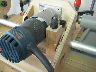
L'ajustement de la mèche de la toupie permet de régler la profondeur de la coupe.